
- News Category
- Industry News
- Product Information
- FAQ
- Customer Cases

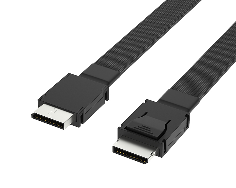
Which factors will affect the transmission quality of Oculink cables?
Oculink Cable Its use in different fields and applications will be affected by various factors. Here are some factors that may affect the transmission quality of Oculink cables:
1. Frequency and bandwidth requirements:Oculink cable is mainly used for high-speed data transmission, with high frequency and bandwidth requirements. If the design and material selection of the cable do not meet the frequency and bandwidth requirements, it may cause signal distortion and reduce transmission quality.
2. Cable length: The length of the cable has a significant impact on the transmission quality. As the length of the cable increases, the attenuation and delay of signal transmission will increase. If the cable is too long, the signal will attenuate and distort, leading to a decrease in transmission quality.
3. Electromagnetic interference: Electromagnetic interference refers to the interference of surrounding electronic devices or interference sources on the cable signal. This kind of interference may come from the magnetic radiation of other electronic devices or lightning, etc. If the cable does not have good shielding performance, electromagnetic interference may cause signal distortion and reduce transmission quality.
4. Interface design: The interface design of the cable directly affects its plug-and-pull performance and stability, thereby affecting the transmission quality. If the interface design is unreasonable, there may be looseness or poor contact during plugging and unplugging, causing signal distortion and reducing transmission quality.
5. Connector quality: The connector is an important part of the cable, and the quality of the connector directly affects the transmission quality. If the manufacturing quality of the connector is unqualified or the material selection is inappropriate, it may lead to unreliable connection, signal distortion, and reduced transmission quality.
6. Environmental conditions: The environmental conditions where the cable is located also affect the transmission quality. Temperature, humidity, pressure and other environmental factors may affect the characteristics of the materials and the stability of signal transmission. For example, in a high-temperature environment, the material of the cable may soften or melt, causing signal distortion and reducing transmission quality.
7. Voltage and current: The transmission quality of the cable is also affected by the voltage and current being transmitted. If the voltage or current exceeds the rated operating range of the cable, it may cause overload or burnout of the cable, thus affecting the transmission quality.
8. Wire quality and manufacturing process: The wire quality and manufacturing process of the cable directly affect the transmission quality. If the wire quality is poor or the manufacturing process is unreasonable, it may cause signal attenuation, interference or distortion, thus reducing the transmission quality.
9. Equipment matching: The transmission quality of the cable is also affected by the connected equipment. If the matching between the cable and the equipment is poor, such as mismatched resistance, capacitance or inductance parameters, it may cause signal distortion and reduce transmission quality. 10. Signal integrity: Signal integrity refers to the degree to which the signal maintains during transmission through the cable. Signal integrity is affected by multiple factors, including signal amplitude, clock synchronization, phase noise, etc. If the signal integrity is low, it may cause a decrease in transmission quality. In short, Oculink cable's transmission quality is affected by many factors, including frequency and bandwidth requirements, cable length, electromagnetic interference, interface design, connector quality, environmental conditions, voltage and current, wire quality and manufacturing process, equipment matching, and signal integrity, etc. To ensure the transmission quality of the cable, these factors need to be comprehensively considered and reasonably designed, selected and tested.
2025-05-26HDMI
High Definition Multimedia Interface (English: High Definition Multimedia Interface, HDMI) is a digital video/audio interface technology, which is a special digital interface suitable for image transmission. It can transmit audio and video signals simultaneously, with a maximum data transfer rate of 4.5GB/s, and no conversion from digital to analog or analog to digital is required before signal transmission.
HDMI can be paired with High-bandwidth Digital Content Protection (HDCP) to prevent unauthorized copying of copyrighted audiovisual content. The additional space in HDMI can be used for future upgrades in audio and video formats. Since the demand for a 1080p video and an 8-channel audio signal is less than 0.5GB/s, HDMI has a lot of room. This allows it to connect DVD players, receivers, and PRRs via a single cable.
2025-05-26<H1>HDMI identification method</H1>
On March 4, 2010, HDMI Licensing, LLC released HDMI Specification version 1.4a on behalf of the original developers of HDMI, which features key enhancements for 3D applications, adds mandatory 3D formats for broadcast content, and includes a Top-and-Bottom 3D format.
Since the term "HDMI 1.4" is too vague to indicate the specific technologies supported by a device, the use of "HDMI 1.4 version" as a version number identifier was completely prohibited in this specification. According to the newly released "Trademark and Logo Use Guidelines", HDMI cable manufacturers are prohibited from using version number identifiers when selling and promoting HDMI 1.4 standard cables. Old cables should remove all version number identifiers such as labels, descriptions, and packaging within one year.
For other HDMI devices besides cables, all version number identifiers must be removed before January 1, 2012. Prior to that date, manufacturers may use version number identifiers provided they clearly specify the technologies used, such as “HDMI v.1.4 with Audio Return Channel and HDMI Ethernet Channel” (HDMI 1.4 version supports ARC audio return channel and HEC Ethernet channel), but the general term "HDMI v.1.4 compliant" (compatible with HDMI 1.4) is strictly prohibited.
2025-05-26HDMI technical advantages
HDMI can not only meet the resolution of 1080P, but also support digital audio formats such as DVD Audio, and support the transmission of digital audio signals in eight channels at 96kHz or stereo at 192kHz. It can transmit uncompressed audio and video signals. HDMI can be used for set-top boxes, DVD players, personal computers, video game consoles, integrated amplifiers, digital audio equipment, and televisions. HDMI can transmit both audio and video signals simultaneously.
HDMI supports EDID and DDC2B, so devices with HDMI have the feature of "plug and play". The source device and display device will automatically negotiate and choose the most suitable video/audio format.
Compared with DVI, the HDMI interface is smaller. The optimal distance of HDMI/DVI cables is no more than 8 meters. With just one HDMI cable, it can replace up to 13 analog transmission lines, effectively solving the problem of messy connections behind home entertainment systems.
2025-05-26<p>HDMI Selection Tips</p>
01: Pay attention to the version of the HDMI cable. The common versions are 1.3, 1.4 and 2.0. It is recommended to buy an HDMI cable of version 2.0, which has a bandwidth of up to 21.8Gbps, supports 3D transmission, can meet higher resolution, refresh rate and color depth, can support high-definition playback above 1080P, and is compatible with the functions of versions 1.3 and 1.4.
02: Pay attention to the size of the HDMI interface. The HDMI interface is divided into standard port and mini port. Due to volume limitations, the HDMI interface on high-definition MP4 players is basically a mini port. Therefore, when selecting an HDMI cable for a high-definition MP4 player, you must look for "standard-mini" HDMI cables, otherwise it won't fit.
03: An HDMI cable is not necessarily better if it's longer. The theoretical transmission distance of a single HDMI cable is 7-8 meters, but in actual use, it doesn't need to be that long. Before buying, it's best to measure the required length, and just leave a margin of 50 centimeters from the measurement result.
04: Choosing a brand HDMI cable is more hassle-free. If you find it hard to judge the quality of HDMI cables by eye, the simplest way is to choose a branded HDMI cable, such as eda, Yabo, Fujicables, Monster, etc. The quality is quite guaranteed!
05: Avoid excessive bending of the HDMI cable. During the use of the HDMI cable, avoid excessive bending of the cable, such as frequent folding or winding may damage the core or shielding layer of the cable. Generally, bending along an arc will not damage the cable.2025-05-26What’s the difference between Oculink cables and USB-C?
Oculink Cable has some functional differences compared to USB-C ports. First, the Oculink cable is a high-speed data transmission line specifically designed to connect the graphics processing unit (GPU) with other hardware components such as expansion cards, displays, and storage drives. It is commonly used in VR (Virtual Reality) and AR (Augmented Reality) applications to provide fast and stable data transmission to support high-definition images and smooth gaming experiences.
By contrast, the USB-C port is a universal connection interface used to connect various devices, including computers, phones, printers, cameras, etc. The USB-C port supports high-speed data transfer, charging, and video output functions, so it is widely applied in various scenarios.
In terms of speed, the Oculink cable generally supports higher data transfer rates. Depending on the specific specifications and versions, the transmission speed of the Oculink cable can reach up to 20Gbps, 32Gbps or even higher to meet the high bandwidth demands of VR and AR applications. The maximum transmission speed supported by USB-C ports is usually 10Gbps, which can meet general data transfer needs but may have bottlenecks in high-demand applications.
Additionally, there are differences in power delivery between Oculink cables and USB-C ports. Oculink cables typically support higher power transmission, providing greater power output to meet the needs of high-performance hardware devices. The power delivery of USB-C ports is relatively lower, mainly used for charging and powering small devices.
Furthermore, there are physical differences between Oculink cables and USB-C ports. Oculink cables usually adopt special slot and plug designs to ensure stable connections and good signal transmission. USB-C ports, on the other hand, use a unified plug design that allows reverse connections, making them more convenient to use. Summarizing, the Oculink cable and USB-C port differ in the following ways:
1. Oculink cables are used for high-speed data transmission and support higher transfer rates, suitable for high-demand applications like VR and AR. USB-C ports are universal connection interfaces supporting the connection needs of various devices.
2. Oculink cables support higher power delivery to meet the energy needs of high-performance devices. USB-C ports deliver power at a relatively lower level, primarily used for charging and powering small devices.
3. Oculink cables use special slots and plugs to ensure stable connections and good signal transmission. USB-C ports use a unified plug design that allows reverse connections, making them easier to use.
In conclusion, although Oculink cables and USB-C ports differ in some functions, they are both designed to meet the connection needs of different devices. Which one to use depends on the specific application scenario and device requirements.
2025-05-26Internal wiring methods for computer cases
Steps/METHODS
Indeed, in the internal hardware connections of the computer case, most connectors and sockets are unique. For example, the 20+4pin of the motherboard and the 4+4pin of the CPU cannot be used interchangeably. The combination of square and round interfaces will not cause misconnections, making it difficult for even beginners to make mistakes. This is considered a very user-friendly design.
However, the connection heads and sockets between the computer case and the motherboard are different. Many slots look alike, and besides USB and audio, they can be inserted either way or even out of order. Due to space limitations, the instructions on the cable and the motherboard are also very simple, which leaves many novice DIY users at a loss.
The USB 3.0 cable inside the computer case
Most mainstream computer cases have audio jacks designed in the I/O area at the front or top, responsible for sound input and output; USB 2.0 and USB 3.0 ports are responsible for connecting 2.0 and 3.0 USB devices; some computer cases also provide card readers or wireless charging functions, all of which need to be connected to the motherboard.
The main cables inside the computer case include Power SW, Power LED, RESET SW, H.D.D LED, F_USB, F_AUDIO, which are the cables for the interfaces and indicator lights on the front panel.
The Power SW and RESET SW cables inside the computer case
Power SW is the most important wiring, short for PowerSwitch, meaning power switch, mainly responsible for controlling the power on/off of the computer host. In fact, its function is to create a short circuit internally; RESET SW is equally important, short for Reset Switch, meaning reboot switch, mainly responsible for controlling the reboot of the computer host.
The H.D.D LED and Power LED cables inside the computer case
Power LED means power indicator light, which is actually the power line of the power LED light; H.D.D LED means hard drive indicator light, which is the power line of the hard drive LED light.
The front USB 2.0 cable and card reader cable on the computer case
The audio connection cables on the computer case
USB refers to the front USB interface, mainly providing power supply and data transmission for the front USB. Some computer cases with card reader functions also use USB interfaces. HD AUDIO is the front audio interface, which is the headphone and microphone jack on the computer case panel. Some older computer cases may use AC'97 interface. If the computer case is designed with a front USB 3.0 interface, the corresponding connector is the blue 19-pin plug. Computer cases with wireless charging function use D-type connectors as power interfaces.
After talking about the computer case, let's take a look at the standards on the motherboard. Corresponding to the cables of the computer case, the motherboard also has corresponding slot areas, namely PANEL or F_PANEL. Many motherboards also provide more functions and slots, and there are certain differences in the design and labeling of different motherboards, which require us to distinguish clearly.
Most motherboards mark the functions of different interfaces in the slot area. Due to the small marking area, some abbreviations differ from those on the computer case cables, so we need to read them carefully. Some pins are rarely used in most cases, and we only need to understand their meanings.
The layout of the PANEL area on the motherboard
The power switch has two pins, possible labels include Power SW, PW, PWR, PWRBTN, POWER, ON/OFF, etc. Short-circuiting the two pins without connecting the computer case can also serve as a power button.
The layout of the PANEL area on the motherboard
The reset switch also has two pins, possible labels include RESET SW, RESET, RES, RST, etc. Short-circuiting the two pins without connecting the computer case can also serve as a reset button.
The label for the power indicator light is often PLED or PWR_LED; the label for the hard drive indicator light is often HDLED or HD.
The front USB 3.0 interface provided by the motherboard
F_USB refers to the front USB interface, where F stands for the abbreviation of front. Similarly, F_AUDIO refers to the front audio interface. Like the computer case design, the blue 19-pin socket on the F_USB 3.0 is the front USB 3.0 interface.
Additionally, there is SPEAKER or SPK, referring to the motherboard's working alarm; IR/CIR indicates the infrared interface; J_PRINT is the printer interface; J_COM is the COM interface.
After explaining the descriptions of the plugs and pins, the wiring should be very easy for everyone. Just connect the corresponding cables to the pins.
The pin with a black vertical line on the base is positive.
There is no sequence for the connections between the computer case and the motherboard, nor is it necessary to connect all the cables to the motherboard. As long as the cables needed for the required functions are connected, the power cord and restart line are essential. Of course, if you use the USB and audio interfaces in the front panel I/O area of the computer case, the corresponding cables also need to be connected.
In fact, the wiring between the computer case and the motherboard is not complicated. What is needed is the user's care and patience. Even novice users without any experience can easily master it after operating it several times by themselves. Successfully completing the wiring can be considered the most challenging work in the assembly process, and the DIY host can then be successfully powered on.
2025-05-26Analysis of the causes of vehicle self-ignition
Analysis of the Causes of Car Spontaneous Combustion
Date of Publication: August 26, 2022 | Reads: 1980
1. Reasons for the spontaneous combustion of car wiring harnesses
With the development of the automotive industry, car circuit problems have gradually attracted worldwide attention. According to incomplete statistics, half of the fuses installed in the world do not meet short-circuit protection requirements, and many vehicles lack fuses. If these vehicles encounter problems, either the wiring harness will burn out or the car will catch fire spontaneously, which is the main cause of current car fires.
In the current cars in our country, the most common fire phenomena such as spontaneous combustion are taxis. In practical car applications, wiring harness spontaneous combustion can be divided into three types. They are overload, short circuit, and fuse blowout, and these three factors directly damage the operation of the car.
1.1 Overload
During the use of a car, if the working pressure on its circuit system and components exceeds the load capacity, it is called overload. Once car parts are overloaded, the electric current in the car becomes too large, causing equipment to heat up, making it prone to short circuits and unable to function properly. Additionally, the internal temperature of the car rises, making self-ignition more likely.
1.2 Short Circuit
In the car's electrical system, when current bypasses the electrical devices and flows directly through the wires, causing the devices to fail to function normally, this is called a short circuit. When a short circuit occurs in the car's electrical system, the current in the internal wires becomes very large, the wire temperature rises, leading to the car catching fire.
1.3 Fuse Blowout
If the fuse and the wire are mismatched, the fuse is prone to burning out. When the fuse blowout phenomenon occurs, the temperature inside the car rises, causing spontaneous combustion. The position of the fuse should also be chosen reasonably; otherwise, the fuse will lose its protective function for the circuit.
2. Influence of Fuse Position and Improvement Measures
2.1 Analysis of Fuse Specifications and Positions
To ensure the normal operation of the circuit system and play the performance of the fuse protecting the circuit, the specifications of the fuse and the selection of wires must be provided in advance. Besides circuit factors, the causes of car wiring harness spontaneous combustion also include circuit factors. Among the circuit reasons that lead to car wiring harness spontaneous combustion, unreasonable circuit design is the main influencing factor.
Firstly, there is a mismatch between the conductors and fuses within the circuit.
Secondly, if the position of the fuse is not scientifically set, once the car's circuit has problems, the fuse cannot provide good protection.
2.2 Analysis of the Fuse Production and Sales Department
The fuses used in cars are small parts, so they are often overlooked. However, their role is very important, and their quality determines the safety performance of the car. According to investigations, half of the car fire accidents are due to poor fuse quality. In the majority of fuse production and sales, fuses do not have clear manufacturers, and there are also issues of poor quality. If the quality of the fuse cannot be distinguished, it can easily lead to car spontaneous combustion. Therefore, when purchasing fuses, you should verify information such as the manufacturer, license number, and manufacturing date.
3.3 Improvement Measures
In the selection of fuses, choose models suitable for the wire, and also select reasonable locations for their placement. Fuses not only lose their protective function for the circuit but also bring a certain degree of burden to the car's circuit system.
For example, in the selection of fuses, using a 30A fuse with a rated current of 22A can choose a 4.0mm2 wire. This way ensures that the specifications of the fuse are reasonable, but it cannot protect 0.5mm2 branch leads. A 0.5mm2 wire may catch fire due to a short circuit, and the 30A fuse cannot blow, losing its circuit protection performance. The most effective method is to install multiple fuses, placing individual fuses near each device.
Through such design, when a short circuit occurs, the fuse can quickly cut off the circuit, avoiding vehicle fires and even fire accidents. In circuit design, not only should the model of the circuit fuse be clearly selected, but also the location and manufacturer of the fuse in the circuit, as well as the sales channel, should be reasonably selected to avoid safety accidents.
2025-05-26Durability test method for harnesses
The durability test of the wire harness is crucial to ensure its long-term stable operation under various harsh conditions. Here are several common durability test methods:
1. Static thermal aging test
Test purpose: Simulate the long-term use of the wire harness in high temperature environments
.
Test method: Place the wire harness in a constant high temperature environment, usually 10 degrees above the maximum operating temperature of the product, for 72 hours
.
Test results: After the test, check the appearance, insulation resistance, and withstand voltage performance of the wire harness to ensure no abnormalities
.
2. Dynamic thermal cycling test
Test purpose: Evaluate the performance of the wire harness under rapid temperature change environments
.
Test method: Cycle the wire harness between high and low temperatures, such as -40 to +125 cycles
.
Test results: Check the functional performance of the wire harness after temperature changes to ensure no damage
.
3. Low temperature exposure durability test
Test purpose: Simulate the long-term use of the wire harness in low temperature environments
.
Test method: Place the wire harness in a low temperature environment of -40°C, for 72 hours
.
Test results: After the test, check the appearance, insulation resistance, and withstand voltage performance of the wire harness to ensure no abnormalities
.
4. High temperature exposure durability test
Test purpose: Simulate the long-term use of the wire harness in high temperature environments
.
Test method: Place the wire harness in a high temperature environment of 10 degrees above the maximum operating temperature of the product, for 72 hours
.
Test results: After the test, check the appearance, insulation resistance, and withstand voltage performance of the wire harness to ensure no abnormalities
.
5. Bending durability test
Test purpose: Evaluate the durability of the wire harness under frequent bending
.
Test method: Use a motor or cylinder to drive the fixture to perform bending tests at specified angles on the wire harness, completing the specified number of bends
.
Test results: Check whether there is any damage on the outer surface of the wire harness and conduct functional tests
.
6. Vibration durability test
Test purpose: Evaluate the durability of the wire harness under vibration environments
.
Test method: Install the wire harness on a vibration table to simulate the vibration environment during actual use
.
Test results: Check the appearance and function of the wire harness to ensure no damage
.
7. Chemical reagent durability test
Test purpose: Evaluate the durability of the wire harness in chemical environments
2025-05-26How to evaluate the reliability of harnesses
评估线束的可靠性需要从多个方面进行测试和验证。以下是根据最新评估线束的可靠性是确保其在各种应用场景中长期稳定运行的关键。以下是详细的评估方法和步骤:
1. 外观检查
检查内容:检查线束的外观,确保没有明显的损坏、磨损、裂纹或老化现象。特别要注意线束的弯曲部位和接头处,这些地方容易出现疲劳和磨损。
工具:目视检查或使用放大镜。
频率:建议每4万公里进行一次全面检查。
2. 电气性能测试
导通性测试:
目的:确保线束的导通性能良好,没有短路或断路现象。
方法:使用万用表或导通测试仪,测量线束端点的电压和电流,计算电阻值。
工具:万用表、导通测试仪。
频率:建议每年进行一次全面的导通测试。
绝缘电阻测试:
目的:确保线束的绝缘性能良好,避免漏电或短路。
方法:使用绝缘电阻测试仪,施加高电压,测量线束导线之间的绝缘电阻。
工具:绝缘电阻测试仪。
频率:建议每年进行一次绝缘电阻测试。
耐压测试:
目的:确保线束在高电压下的绝缘性能。
方法:对线束施加一定时间的高电压,测量线束上的电流,判断是否超过设定值。
工具:耐压测试仪。
频率:建议每两年进行一次耐压测试。
3. 机械性能测试
拉伸测试:
目的:评估线束在机械应力下的性能。
方法:使用拉力测试仪,对线束施加拉力,记录其断裂强度。
工具:拉力测试仪。
频率:根据使用环境,建议每两年进行一次拉伸测试。
弯曲测试:
目的:评估线束在频繁弯曲下的耐久性。
方法:使用弯曲测试仪,对线束进行规定角度的弯曲测试,并完成规定次数的弯曲。
工具:弯曲测试仪。
频率:根据使用环境,建议每两年进行一次弯曲测试。
4. 环境适应性测试
高温测试:
目的:评估线束在高温环境下的性能。
方法:将线束置于高温环境箱中,保持一定时间,观察其性能变化。
工具:高温环境箱。
频率:根据使用环境,建议每两年进行一次高温测试。
低温测试:
目的:评估线束在低温环境下的性能。
方法:将线束置于低温环境箱中,保持一定时间,测试其柔韧性和电气性能。
工具:低温环境箱。
频率:根据使用环境,建议每两年进行一次低温测试。
湿热测试:
目的:评估线束在潮湿环境下的性能。
方法:将线束置于高湿度环境中,保持一定时间,测试其性能。
工具:湿热测试箱。
频率:根据使用环境,建议每两年进行一次湿热测试。
5. 电磁兼容性(EMC)测试
辐射发射测试:
目的:评估线束在工作时的辐射水平。
方法:通过天线测量线束在工作时的辐射水平。
工具:电磁干扰测试仪。
频率:建议每年进行一次辐射发射测试。
辐射抗扰度测试:
目的:评估线束在电磁干扰下的工作性能。
方法:检测线束在电磁干扰下的工作性能。
工具:电磁干扰测试仪。
频率:建议每年进行一次辐射抗扰度测试。
6. 耐久性测试
机械疲劳测试:
目的:评估线束在机械应力下的耐久性。
方法:对线束施加机械应力,如振动、弯曲、扭转等,记录其耐久性。
工具:振动测试台、弯曲测试仪。
频率:根据使用环境,建议每两年进行一次耐久性测试。
7. 记录和维护计划
记录:
内容:记录每次检查、清洁、更换的时间和内容。这有助于跟踪线束的使用状况,及时发现潜在问题。
工具:记录本或电子表格。
频率:每次检查后记录。
维护计划:
内容:制定详细的维护计划,确保线束的维护工作能够按时进行,避免因疏忽而导致的设备故障或安全事故。
工具:维护计划表。
频率:根据使用环境,建议每半年制定一次维护计划。
2025-05-26